


SC-FRQ03 Frequency Condition
 This panel allows simulator administrators to manually set frequency conditions on the frequency analysis proximity grid SC-FRQ01 to be viewed by the simulation crew.
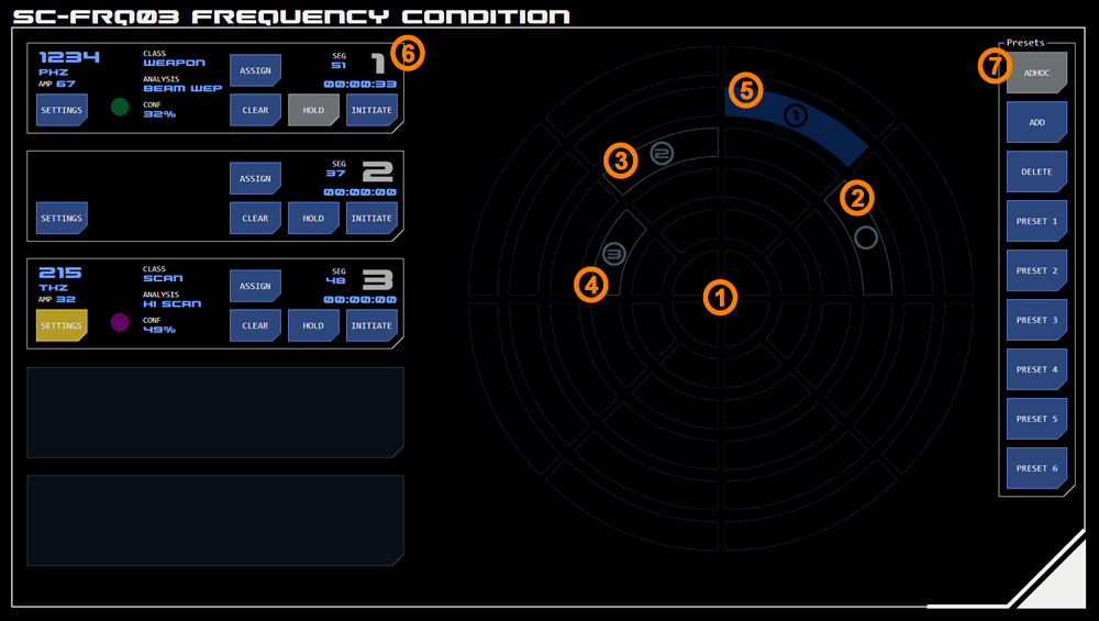
The layout of the two panels is similar, with a standard proximity grid to the right and monitors for selected grid sectors on the left.
1. Proximity Grid
Any sector on this grid may be selected by tapping its centre. For active or selected sectors the circular indicator shows where to tap - for inactive sectors the same indicator area must be tapped so the operator must estimate the indicator's position.
Sector States
Sectors may display one of these states:
2. Selected
The sector has been selected and is ready to be assigned to a monitor so that settings can be applied.
Tapping a selected sector again will cancel the selection.
3. Monitored and Ready to Set
This sector has been assigned to a monitor (the monitor's designation is displayed in the circular indicator at the centre of the sector) but is not yet active.
In this example, no settings have been made in the corresponding monitor (monitor 3). Tapping the SETTINGS button will allow settings to be applied so the sector can be initiated.
4. Monitored and Ready to Initiate
The sector has been assigned to a monitor (the monitor's designation is displayed in the circular indicator at the centre of the sector) but is not yet active.
In this example, settings have been made in the corresponding monitor (monitor 2) as indicated by the alert state of the SETTINGS button. These settings will be applied when the sector is initiated.
5. Active
A sector that has a solid colour is currently an active detection and is visible on on the frequency analysis proximity grid displayed on panel SC-FRQ01. The number within the circular indicator corresponds to the monitor the segment is assigned to.
A sector that has a solid colour but no number within the circular indicator is an active detection, but not currently being monitored. This may be because the sector was unassigned from the monitor (see the ASSIGN button below) or the panel was reset while detections were active. Tapping the sector will allow it to be assigned to a monitor to be cleared.
6. Sector Monitors
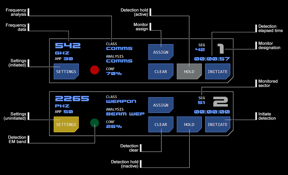 Up to five sectors can be assigned to the monitor section. Once assigned, settings can be applied to the sector and it can be initiated, when it appears as a detection on the frequency analysis panel SC-FRQ01 to be viewed by the simulation crew.
If settings have been applied (see below) they will appear in the monitor. Frequency data (including the EM Band) and frequency analysis will be visible to the simulation crew on the frequency analysis panel.
At the top right is the monitor's designation which corresponds to the grid sector being monitored. In addition, the sector's co-ordinates (the first numeral is diametrical position, the second is radial position) are displayed.
The elapsed time since the detection's initiation is displayed (this is also visible to the simulation crew on the frequency analysis panel).
Function Buttons
Buttons on the monitor have the following functions.
Assign
Tapping the ASSIGN button clears the monitor (even when a detection is active) so that another sector can be be assigned to that monitor, without deactivating the detection.
Care should be taken when using this function especially when a sector is on hold, as while a sector unassigned using this function can later be reassigned to a monitor but its settings will not be available. New settings will need to be entered, or the sector deactivated by tapping the CLEAR button.
Clear
Tapping the CLEAR button clears the monitor of the sector that has been assigned to it (unless the sector is active).
The CLEAR button will also deactivate and clear an unmonitored detection.
Hold
The HOLD button toggles the detection between transient or continuing modes.
If the HOLD button is in selected state the detection will continue to be active beyond the normal display period until the hold is released (by tapping the HOLD button again).
If the hold is released within the normal display period, the detection will remain active until the original display period ends.
Initiate
The INITIATE button initiates the monitored sector as an active detection using the currently set parameters (where it is visible to the simulation crew on the frequency analysis panel) and starts the elapsed timer.
If too few parameters have been set the INITIATE button will flash alarm state and indicate DATA MISSING without the initiation proceeding.
The detection's parameters can be changed after it has been initiated and while it is active by tapping the SETTINGS button (see below). Tapping the INITIATE button while the detection is still active will apply any changed settings and restart the elapsed timer.
If no settings were changed, only the elapsed timer will reset.
Settings
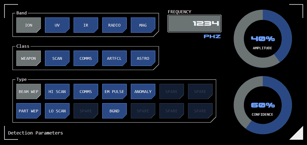 The SETTINGS button is used to access the detection parameters overlay.
Parameters are applied as they're entered, so once entry is complete the overlay can simply be closed.
Band
This allows the EM band of the detection to be selected. The frequency unit - ranging from PHz down to MHz (or telsa for magnetic detections) - will automatically adjust to reflect the selected band.
Class
This allows the analysis class of the detection to be selected.
Type
This allows an additional analysis code to be selected.
Frequency
This allows the frequency of the detection to be entered.
Amplitude
This allows the amplitude (intensity) of the detection to be selected, from a range of 0 - 100. As well as displaying numerically this value also changes the frequency visualisation on the frequency proximity analysis panel SC-FRQ01.
Confidence
This allows the AI's confidence in its analysis to be entered (as a percentage, with 100% indicating absolute confidence in the analysis).
7. Presets
This button group allows access to a number of preset detections.
Tapping a PRESET button will display the preset detections on the grid as monitored and ready to initiate, with parameters displayed in the corresponding monitor.
Adhoc Mode
By default the panel is in ADHOC mode with no detections or sectors displayed or monitored.
Tapping the ADHOC button will clear any inactive detections or sectors.
If the ADHOC button is taped while detections are active it will flash alarm state and indicate ACTIVE, preventing the detections from being cleared.
Editing Presets
Presets can be added, updated or deleted.
Adding a Preset
Here.
Updating a Preset
Here
Deleting a Preset
Here
Concept Site
Immersive sci-fi and how to join the adventure
Crew Site
Information and tools for ISDC crew members


