


generating PDN schematics
PDN schematics appear frequently on vessel consoles, to assist with the management and monitoring of power distribution to the systems controlled by the console.
Where a PDN schematic is required on a console, a schematic module is added in the required space using the Console Designer. The schematic may then be drawn in that space (or a pre-drawn schematic added).
Schematic Canvas
 Schematics may be drawn or modified by putting the schematic into canvas (or edit) mode. It is recommended that the schematic layout is refined in vector-based drawing software prior to working with the schematic canvas.
Components are positioned on the schematic canvas using x and y co-ordinates.
Creating a new schemtic canvas requires the defition of the canvas width and height. In canvas mode, the schematic canvas displays a grid with minor gridlines representing 10 pixels and major lines representing 100 pixels.
Also, the relevant co-ordinates of conduits and node conduit taps are displayed to assist the drawing process.
Draw Conduits
Conduits can be drawn horizontally or vertically. A conduit is drawn by selecting the conduit orientation (vertical or horizontal), defining the start point (using x and y co-ordinates) and then defining the length of the conduit. Where a cnduit needs to be drawn from right to left or from bottom to top, select the reverse option to ensure the conduit is drawn correctly.
In edit mode, a conduit’s main positioning value is displayed (x co-ordinate for vertical conduits, y co-ordinate for horizontal conduits) to assist with positioning other components. By default, this co-ordinare is displayed in the center of the conduit. Where this conflicts with the display of other co-ordinates (from connecting conduit taps, for example) the co-ordinate display can be offset by entering the required distance in the offset option.
Conduit Control
A conduit control should be positioned near the conduit it controls (preferably a vertical conduit). Conduit controls have two orientations, allowing them to be placed to the left or right of a conduit. The double-line of the conduit should be adjacent to the controlled conduit.
Conduit controls can be placed above or below a conduit if needed, although this should be avoided.
Add Nodes
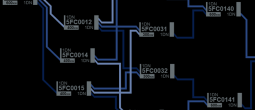
Nodes are added to the schematic canvas by selecting the node type, orientation and position. The node’s position is calculated from the top left corner of the node.
Node types: include distribution nodes and system (consumption) nodes.
Node orientation: the node’s upstream interface can be positioned on the left or the right of the node, to suit the desired schematic layout.
The node symbol must then be associated with the node it represents, by entering the node’s designation.
Node Conduit Taps
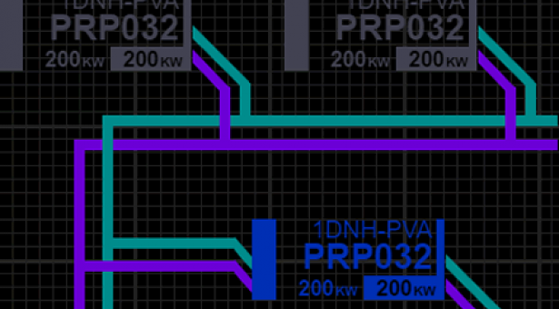
Up to three node taps can be defined on both upstream and downstream interfaces. Node colours are set by default to standard (purple for conduit 1, green for conduit 2, blue for conduit 3) but this can be overridden if required.
The orientation of the node taps also needs to be defined. Vertical taps are used to connect to horizontal conduits. Horizontal taps are used to connect to vertical conduits. All of the taps on an interface must be the same orientation, but upstream and downstream interfaces may have different tap orientations.
To connect a node tap to a conduit, the end-point of the tap’s tail needs to be defined. For horizontal taps, define the x co-ordinate of the target conduit (the conduit’s x value will be displayed on the conduit). For vertical taps. Define the y co-ordinate of the target conduit. In canvas mode, the x and y co-ordinates of the tap's end point are displayed, with the end point indicated by a white sqaure.
Categories:
Concept Site
Immersive sci-fi and how to join the adventure
Crew Site
Information and tools for ISDC crew members


