


Held Bearing Execution
A held bearing is where a set bearing is automatically executed every maneuvering cycle until stopped. This makes the vessel follow a circular course. This is useful for when a traversal maneuver is required, or when a large heading change needs to be broken down into smaller maneuvers.
The radius of the circular course is determined by the vessel’s speed and the chosen bearing. The Held Bearing Calculator (HBC) on the Impulse Maneuvering panel calculates the required bearing based on the desired course radius and vessel speed.
Usecase: Search Grid
A search grid typically requires a vessel to follow a reciprocating course with a specified distance between so as to ensure efficient and thorough coverage of the search area. Executing a held bearing when the edge of the search area is reached ensures that the next leg of the search pattern is the correct distance.
To execute, the held bearing is engaged at the gird co-ordinates specifying the edge of the search grid. The held bearing continues until the vessel has come about – the vessel’s heading is 180° more (if the maneuver is to port) or less (if the maneuver is to starboard) than the initial heading.
Usecase: Traversal
 Traversal of an Astronomical Object (AO) can be an efficient way to maintain a course that gains the protection of the AO’s shadow (to mask EM emissions, for example). An impulse traversal should not be confused with establishing orbit, which would be achieved using RCS maneuvering.
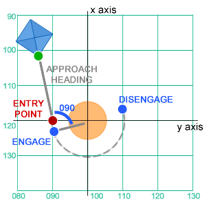
Approach Heading
A traversal is calculated against the grid co-ordinates at the centre of the maneuver, which usually the AO’s grid co-ordinates. From this the entry point for the maneuver is calculated, which is used to calculate the approach heading. The entry point for the maneuver is approximated by adding or subtracting the desired traversal radius from either the X or Y axis, depending on the vessel’s heading and whether the maneuver will be to port or starboard.
A guide as to which axis to use is in the table below. Add or subtract the traversal radius to the axis as indicated.
The maneuver will be more accurate the closer to an axis heading (000, 090, 180 or 270) the approach is.
|
Approach Heading |
Maneuver |
Axis |
|---|---|---|
|
315 - 045 |
Port |
+ Y |
|
Starboard |
- Y |
|
|
045 - 135 |
Port |
- X |
|
Starboard |
+ X |
|
|
135 - 225 |
Port |
- Y |
|
Starboard |
+ Y |
|
|
225 - 315 |
Port |
+ X |
|
Starboard |
- X |
Use the Intercept Bearing Calculator (IBC) to set the correct approach heading to the point.
Engage Bearing
The maneuver will not begin at the entry point. Instead, the beginning of the maneuver is calculated when the AO's grid co-ordinates are abeam.
Once the approach heading is set, enter the AO’s grid co-ordinates (representing the centre of the maneuver) into the IBC. You’ll use the IBC’s bearing display to decide when to engage the held bearing maneuver. When IBC shows a bearing of 090 (for a port maneuver) or -090 (for a starboard maneuver), this means the AO is abeam - engage the maneuver.
The exit point for the maneuver is indicated by the change in the vessel’s heading, based on the desired extent of the traversal.
For example. with a 180° traversal, add (for a port maneuver) or subtract (for a starboard maneuver) 180 to the approach heading. When the vessel’s heading reaches this heading, disengage the maneuver.
Concept Site
Immersive sci-fi and how to join the adventure
Crew Site
Information and tools for ISDC crew members


