
NV-IMP03 Impulse Navigation Panel
 The Impulse Navigation panel assists with the navigation of pre-plotted courses during impulse operations.
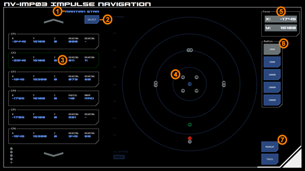
The panel consists of a scrollable list of course points and a 2D impulse map displaying the location of the course points, Astronomical Objects (AOs) and the vessel.
Course Relative to Focus
Courses are relative to the panel's current focus. Changing the focus will update all course points accordingly.
Course Point List
This scrollable list displays the course points included with the selected course. An example course point is shown at (3). Courses are chosen from a list using the select button (2). The current course title (1) is displayed at the top right of the list, above the select button.
Each course point includes the grid co-ordinates, the heading required from that course point, and the bearing required to achieve that heading. The first course point does not show a bearing as this is dependent on the approach heading.
The specific course point currently being navigating towards is highlighted green (as is the corresponding dot on the map). On loading the panel the first course point is highlighted by default. The highlight can be moved by tapping the desired course point. To remove the highlight, tap the already highlighted course point.
When the vessel navigates within a certain radius of the current course point the highlight automatically moves to the next course point. The default radius is adjustable using the dialog under the course selection list.
When a new course is selected it may include default radius and focus information. If so, the impulse map will automatically update with this new configuration.
Maneuver Types
Data layout changes if particular maneuver types are specified.
Radial Maneuver
A radial maneuver requires a bearing applied over a series of maneuvering cycles that results in a circular course of a particular radius.
A radial maneuver has two course points. The entry course point has a maneuver type of RAD and specifies the radius required for the maneuver (instead of displaying a heading). In the example panel image, CP4 is the entry course point for a radial maneuver.
The exit course point displays the heading required at the end of the maneuver, but displays the number of maneuvering cycles required to reach that heading (instead of displaying a bearing). The number of maneuvering cycles is calculated based on the currently selected cruise speed and the radius specified in the entry course point. The underlying calculation is the same used by the Held Bearing Calculator (HBC). In the example panel image, CP5 is the exit course point for a radial maneuver.
Impulse Map
The impulse map (4) displays course points as silver dots, with the point’s order number displayed in the centre. The currently highlighted course point is displayed as a green dot.
Where multiple course points overlap, the earliest course point will be displayed until the vessel navigates beyond the following course point, after which the later course point will be displayed.
Stars are displayed as yellow dots with their designation listed below. Other AO’s are displayed as blue dots with their system number displayed in the centre.
Other impulse map features such as the ability to set the map’s focus co-ordinates and radius (scale) work as normal. Focus and radius may be updated automatically when a new course is selected, although this can then be overridden by the user.
The Point-of-Interest feature is also available on the map.
Markup and course trail options can be activated at the bottom right of the map ((7).
Free Navigation Mode
Tapping the FREE NAV button hides all course points. This allows the impulse map to be used as a navigation guide.
For example a desired course could be drawn up by the quartermaster using the markup tool and the POI used to identify the grid co-ordinates and bearing of each point on the course.


