


Poloidal Generator Simulator
Poloidal Field Generators (PGEN) manipulate the main containment field to optimise plasma flow characteristics with carefully-tuned complementary magnetic fields, using the principles of magnetic field dynamics.
The poloidal generation system manages the output of these generators against power input into them. As the poloidal containment field needs to be significantly less powerful than the toroidal field to be effective, operating temperature efficiencies are of less concern.
Overview
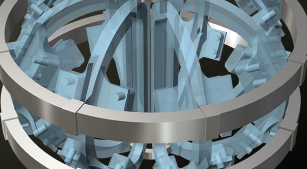
There are four Poloidal Field Generator systems (PGENs) used to modify the main magnetic containment field produced by the Toridal Field Generators (TGENs), improving plasma flow. This is achieved by applying a less powerful magnetic field to to main containment field in order to reduce the variance in magnetic field shape that naturally occurs as the main containment field gets further from its toroidal generator.
The shape of the containment magnetic field is monitored along the Active Field Plane (AFP), which plots all points along the magnetic field with the same magnitude. For the AFP, this magnitude is fixed at the level of lorentzian force needed to repel (and thereby contain) charged particles of the type used in the reaction plasma. The AFP naturally curves as it moves away from toroidal generators. The gradient of this curve is referred to as the Containment Field Pitch (CFP), with higher curve gradients (higher CFP values) inhibiting plasma flow. It is the role of the poloidal magnetic field to reduce the CFP so as to improve plasma flow.
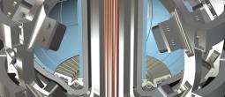
Poloidal generators are less powerful than toroidal generators and are constructed slightly differently. The poloidal generators are not identical, reflecting the physical shape of the reactor chamber- the inner diameter of the torus is smaller than the outer, so the inner generators need to produce less energy for the same effect and so are smaller.
Power supply for each poloidal generator is managed independently. The output from a poloidal field generator is a magnetic field, the magnitude (strength) of which is measured in teslas (T). The magnitude produced by the generator at a given power input level is described by the generator's response profile (defined below).
Measurement and Visualisation
The containment field is generated by the combined output of two toridal generators, which forms a segment. These segments are repeated eight times around the reactor to create a complete torus. 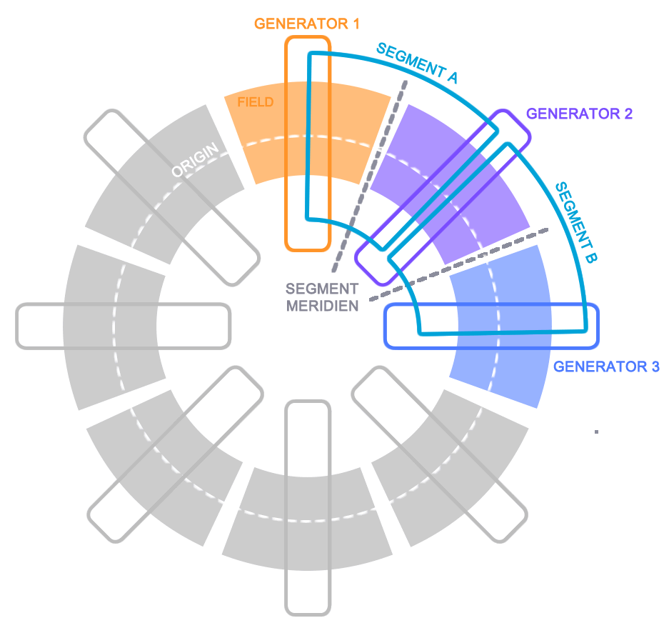 The poloidal field operates within each segment and so requires differing measurement conventions to the toroidal field (which is measured against each toridal generator).
Meridian
The meridian is a plane representing equal distance between the toroidal generators forming the segment. This marks the inflection point between the output of the facing generators. The segment is measured in degrees from the meridian, with measurements to the left of the meridian (plasma counter-flow) measured as negative integers. Each segment is 45 degrees in size.
Origin
The origin represents the point where the output from all facets of the toroidal generator is common (theoretically for a properly tuned generator this should be a single point in the centre of the toroidal generator).
Power Response Profile
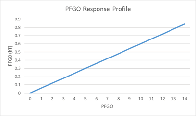 The nature of the magnetic field required from the poloidal generators for field dynamic purposes results in far less efficient output. Given their relatively low output (when compared to the toroidal generators) the poloidal generators have a fairly linear power response profile but as a result are not sensitive to environmental heat load.
However at higher power levels the generators are prone to overheating which in extreme cases could see parts of the superconducting coils fuse, impeding operating effectiveness.
This is managed as an engineering event which becomes increasingly probable outside of safe operating range (and almost certain beyond maximum design limits).
Early modeling suggests that nominal power input (PFGI) is around 7 units.
Function
where x is the power units input and m is a modifying constant.
Operating Factors
For the purpose of containment field dynamics the most useful measure of toroidal field output is the lorentzian (repulsive) force applied by the field to the charged particles making up the reaction plasma, rather than the raw output of the toroidal generators. This is measured in Amperes per meter (A/m).
Active Field Plane (AFP)
The AFP is a constant, representing a plane where all points are equal to the amount of lorentzian force required to contain charged particles in plasma of the type used in the reactor.
Applied Toroidal Force (ATF)
The AFP represents a constant measure of lorentzian force but its position inside the reactor chamber will vary depending on toroidal output (field lines of a given magnitude manifest further from the generator as generator output increases). To calculate the Active Field Plane Focus (AFPF - see below) an additional variable complementary to AFP is required, describing a fixed position but variable lorentzian force. Applied Toroidal Force (ATF) is a measure of the lorentzian force currently being applied by the field to a constant position: A field plane representing the nominal Reaction Volume (nRV)).
Outputs
The outputs of the poloidal simulation are passed back to the toroidal generator simulation to allow calculation of the Effective Reaction Volume (ERV).
Active Field Plane Focus (AFPF)
 Describes where in the reaction chamber the Active Field Plane (AFP) manifests. This is measured in meters from the origin (see above). As the AFPF bounds the volume containing the reaction, it is used by the plasma system to calculate the effective Reaction Volume.
The interaction of each toroidal generator's magnetic fields causes field lines from each to deviate towards each other, creating in combination a closed curve within the segment.
Function
The segment's combination curve can be described by the Witch of Agnesi function:
where x is the distance from the meridian (in degrees) and a is the ATF (the mathematical radius of the function).
Modifier
The output of the Witch of Agnesi function is then modified to fit the physical dimensions of the reactor chamber
Containment Field Pitch (CFP)
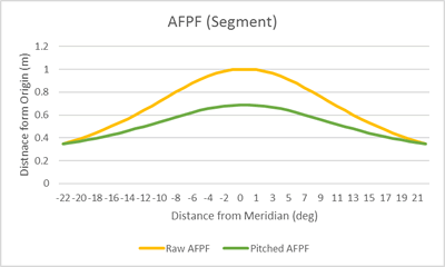
The containment field pitch describes the impact the poloidal field generator's output has on the AFPF. Expected behaviour is a shallower curve with the most promounced impact at the meridien and minimal impact at the generator.
A flatter (smaller) CFP means smoother plasma flow. This is used by the plasma drive system when calculating plasma flow characteristics.
To generate the modified curve, the AFPF function's raw values are modified, so that at a given distnace from the meridien:
where a is the raw AFPF value at the distnace from meridien, p is PFGO and n is a modifier (the raw AFPF value at the generator or 22 degrees from meridien) which ensures both curves have the same value at the generator.
Function
CFP can be expressed as a value descibed by how shallow the AFPF curve is
where a is the AFPF value at meridien (either raw AFPF or modified AFPF depending on which is being measured) and m is the minimum (unmodified) AFPF (ie AFPF at 22 degrees from meridian).
Future Expansion
The process of averaging poloidal outputs to calculate against each toroidal generator is highly simplistic and for MVP launch only. This is an area where more sophisticated modeling might be added later. For example:
Intra-Segment Poloidal Adjustments
In the current model, power input is applied to the whole poloidal generator. This means that poloidal adjustments per segment are not possible.
It is conceivable that the generators could be constructed in such a way that some adjustments to poloidal output on a per-segment basis might also be made possible.
Intra-Segment Quadrants
In the same way the reactor is divided into 8 segments along the x plane based on toroidal generators, it might also be divided into four quadrants on the y plane based on poloidal generators. In this way, each segment might have four quadrants independently influenced by each of the four poloidal generators.
Categories:
Attachment:
Concept Site
Immersive sci-fi and how to join the adventure
Crew Site
Information and tools for ISDC crew members


