


TL-WDR01 Firing Solutions
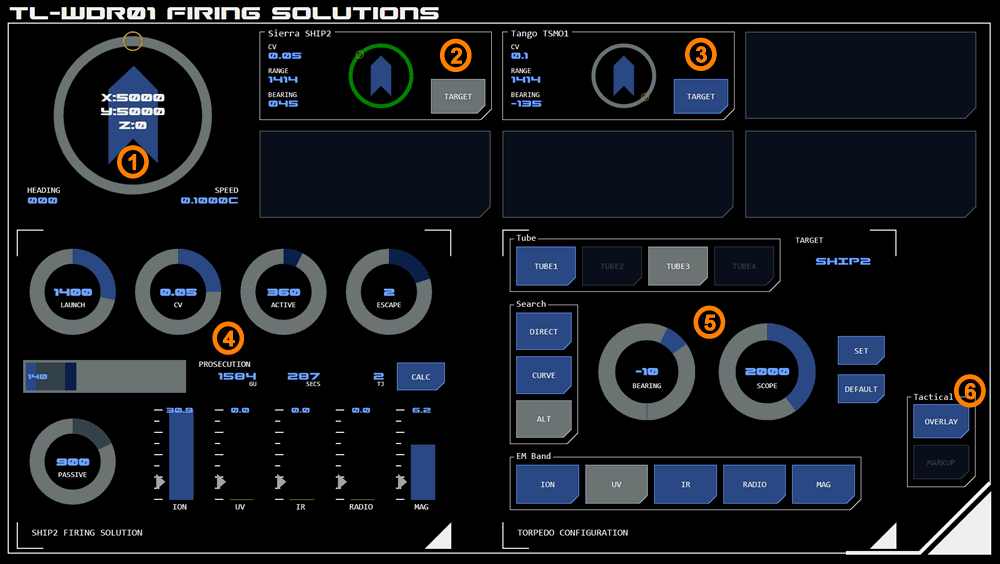 This panel allows operators to calculate optimal torpedo launch and configuration options for successful prosecution.
Panel Components
The panel is used for calculating and configuring optimal launch and flight conditions for torpedoes. It displays all available tracked contacts which can be selected as targets for both a firing solution calculator and a torpedo configuration module.
1. Compass
The panel includes a 'compass' module which displays the vessel's current position, speed and heading - providing useful context for targeting purposes.
Target Display
Up to six contacts can be tracked by the vessel at any one time due to the number of narrowband EMDAR arrays available. The contacts currently being tracked are displayed here.
The format of this display is similar to that used by the EMDAR Contacts Board, although the data displayed is slightly different. For example, the contact's closing velocity (CV) is displayed, which is the difference in speed between the contact and the user's vessel (a positive value indicates the contact is slower than the user's vessel).
2. Selected Target
Tapping the target button makes that contact's data available to firing solution calculator and assigns the contact as the target for the torpedo configuration module.
The target button is displayed in active mode and the radial track behind the contact position visualisation is emphasised in green.
Tapping the target button again will deselect the target without setting a new target.
3. Unselected Target
Other contacts available for targeting can be selected by tapping their target button. This replaces any previous target for both the firing solution calculator and torpedo configuration module.
4. Firing Solution Calculator
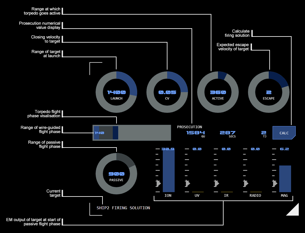 The firing solutions calculator allows the operator to explore a number of different range and phasing alternatives for a torpedo’s flight. It allows different conditions for torpedo launch and running time to be assessed for optimal target prosecution.
Each phase of the flight has its own colour code (reflected in the dial and visualisation colours).
Launch (Light Blue)
The launch phase has two dials:
LAUNCH: selects the range to the target when the torpedo is to be launched
CV: Selects the closing velocity (CV) to the target expected at launch.
Wire-Guided Phase
The wire-guided phase is part of the launch phase. Its range isn't set directly, but is calculated by subtracting the active and passive ranges from the launch range. The wire-guided range for a calculated solution is therefore also displayed numerically on the flight phase visualisation.
Active (Dark Blue)
The active (final) phase has two dials:
ACTIVE: Selects the expected range to target when the torpedo goes into active mode.
ESCAPE: Selects the expected opposite thrust the target is expected to be able to apply to escape the torpedo once it goes into active mode (and is detectable).
Passive (Dark Grey)
The passive phase has a single dial, which selects the range the torpedo is expected to fly in passive mode (ie not in either wire-guided or active modes).
TARGET AMBIENT EM: The target's ambient EM at the selected passive range is displayed, so that you can see whether there is sufficient EM coming from the target for the torpedo to detect. Any value below the minimum detectable EM (indicated for each band) will trigger alert status for that band.
Calculation Display
Once values have been set, calculation is triggered by tapping the CAL button. The results of a firing solution calculation are displayed horizontally to the left of the CALC button.
If any required values are not set, the button will flash alarm status and display an error message indicating which value is missing.
If the set values do not result in a successful prosecution the button will flash alarm status and display a RANGE error message.
Range Visualisation
The range of each flight phase is displayed on a horizontal bar graph visualisation. The light grey background indicates the maximum range (by default 5000GUs).
The range of the wire-guided phase is also displayed numerically at the far left (as this range is not set directly and so is not otherwise displayed anywhere else).
Prosecution Results
Numerical results for prosecution are displayed. The calculator uses the vessel's current speed to assist in calculating these results.
From left to right the results are:
RANGE: The expected range of the torpedo's flight before successful prosecution (measured in GUs).
ELAPSED: The expected time elapsed from launch to successful prosecution (measured in seconds).
DAMAGE: The amount of kinetic energy expected at the time the torpedo hits the target (measured in terajoules).
5. Torpedo Configuration
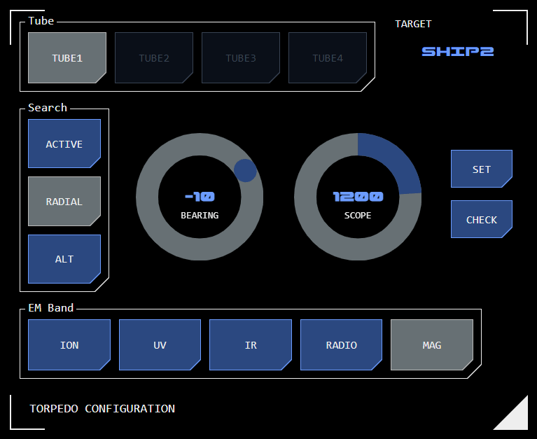 The torpedo configuration module allows flight search parameters to be added to a loaded torpedo.
Tube Selection
Select the tube that is to be configured. All torpedoes loaded into the tube will receive that configuration. This allows each tube to be assigned specific role within a complex tactical engagement.
The calculator's settings do not change when a new tube is selected. This makes it easier to close tube configurations across tubes. To see the selected tube's configuration, use the CHECK button (see below).
Target
The currently selected target is displayed here. The target is selected from the target board (see above).
Wild Launch
If no target is selected, the torpedo will be fired "wild". Passive search settings will be applied to the first EMDAR data detected (although this will be overridden by the torpedo's IFF system if required).
When setting the configuration without a target, the target display will flash alert mode to prompt the user to confirm they intended this, although the torpedo configuration will still be set.
Search Pattern
The search buttons select the required search pattern for the passive flight phase. The torpedo's EMDAR system covers an arc +/-45° ahead.
Selection radials will display appropriate to the search pattern selected.
Active
This button allows the range from target that automatically triggers the torpedo's active guidance system. Default is 100 GUs.
Where a passive search pattern has been selected (see below) tapping this button will cancel that search pattern and configure the torpedo with a linear course while in passive mode.
Radial
A radial search pattern is defined by the bearing and scope settings. The torpedo will adjust its course so that the bearing (to a maximum of 90°) is completed over the distance (in GUs) set as the scope. It will then resume a linear course.
This search pattern is useful for following a target's course if it is traveling on a course perpendicular to the vessel.
Alt
An alternating (ALT) search pattern (or zig-zag) alters the torpedo's original heading by the bearing selected (to a maximum of 45°), alternating between positive and negative bearings each time the scope time (in seconds) is reached.
This search pattern increases the area of space the torpedo can cover with its EMDAR system.
EM Band
This selects the EM band the torpedo's EMDAR system should use. Torpedo-mounted EMDAR is not as powerful as the vessel's EMDAR system and can only process data from a single band.
Set Button
This button applies the selected configuration to the selected torpedo.
If required parameters are not set, the button will display alarm mode and display an error message indicating the missing parameter.
Check Button
This button displays the current configuration for the selected tube. For display purposes it temporarily replaces existing control settings but these do not become effective until the SET button is tapped.
While the check is active, the target will be displayed with alert status to indicate the check configuration (not the current control status) is being displayed. Changing the target on the target display will not be reflected in the configuration module while the check is active.
The check is cleared when any other button in the configuration module is tapped (tapping the check button does not toggle the check off). To simply clear the check without making any configuration changes, tap the currently selected tube.
5. Tactical Overlay
Tapping this button displays the tactical overlay.
Attachments:
Concept Site
Immersive sci-fi and how to join the adventure
Crew Site
Information and tools for ISDC crew members


